
DISCLAIMER: This works fine, but I take no responsibility for any screw ups on your end. You really need a multimeter with to test these connections out. The risk of screwing it up exists. Don’t modify things you aren’t prepared to lose.
TLDR: If you just want to know how to modify a device to add a headphone jack then scroll down to the drawings rather than the photos.
I have a wide range of talents, however I must admit that the particular talent of piano player/keyboardist is notably absent amongst these achievements. In fact I have reached the point where I may have to face the hard fact that I have no perceptable musical talent whatsoever.
This wouldn’t be a problem in the slightest except for three factors;
- The first factor is that I like electronics and I am at some level convinced that practice will eventually ameliorate this musical ineptitude. Usually the desire to practice these things happens at somewhat antisocial times of the day. This is because I am me.
- The second factor is that I am somewhat slightly deaf (What?) This is mainly something that I was born with and which I thus mostly forget about, but it can be an irritation at times, mainly to other people.
- The third factor in play is the fact that I live in a block of flats, they are about 100 years old and built of double skin brick (which makes for good neighbours), but I do have neighbours downstairs who I don’t normally wish to irritate for no reason.
So of course when faced with the prospect of buying a Casio CTK-50 for very cheap at a thrift store I gave due consideration to the fact that it has no native means for quiet individual enjoyment (no headphone jack), Then I went ahead and bought it anyway.

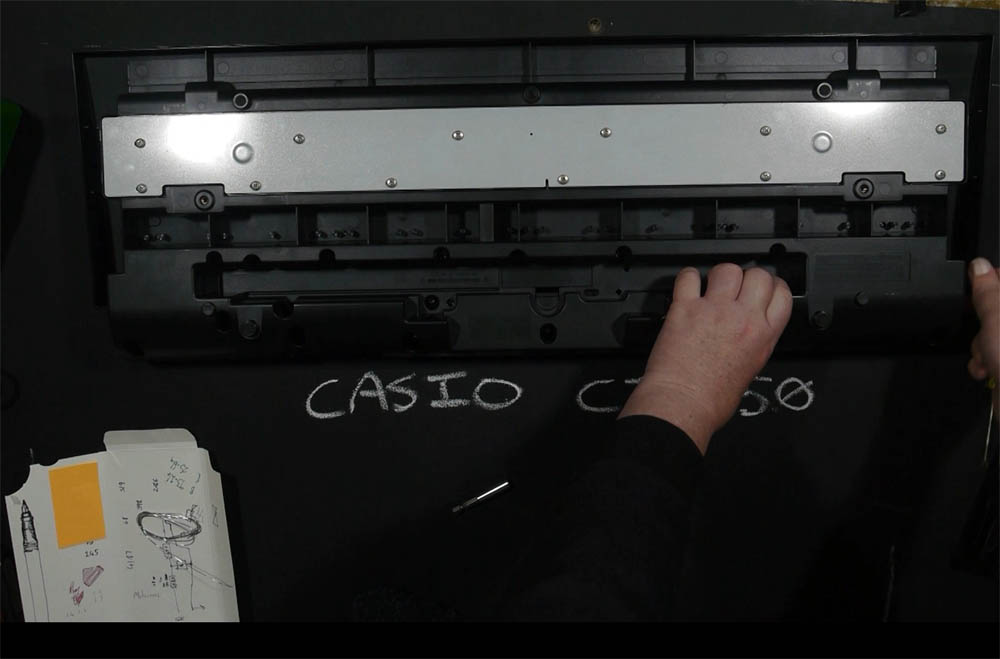
So, in a fit of momentary sensibility I found a schematic for the device, and then went ahead and opened it up for modification. The back of the keyboard has lots of screws holding it together, I removed basically all of them except for those on the grey metal – those are for the keyboard module, which isn’t really hacker friendly (you can get into it, but there’s not much to do when you get there).
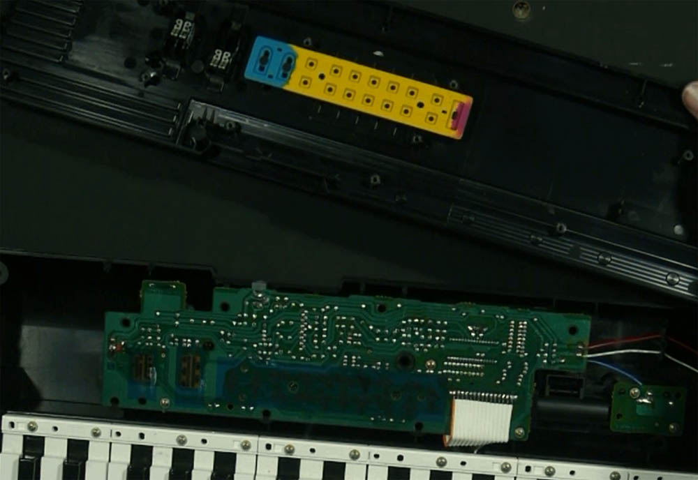
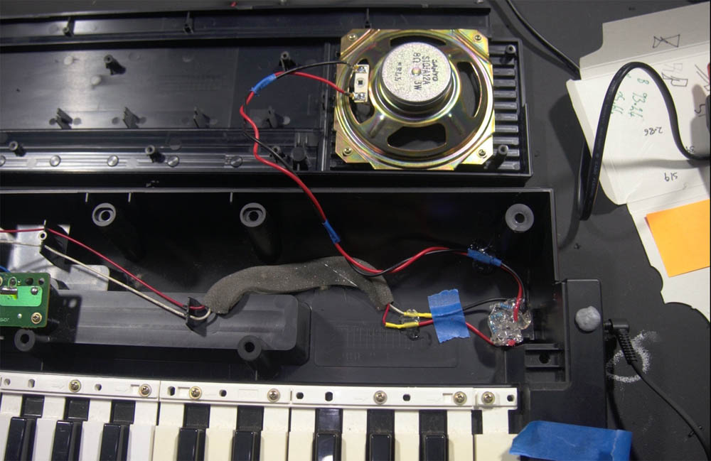
This is what you see when you get in there. As a side note, if you want to circuit bend one of these or work on it whilst it’s open you’ll need to solder onto the solder points to do so. The buttons on the yellow and cyan part are all carbon pads, and the switches on the left (power and volume) run on printed carbon. On the plus side the traces are nice and big, all through hole and there is plenty of space in the keyboard to stuff stuff.

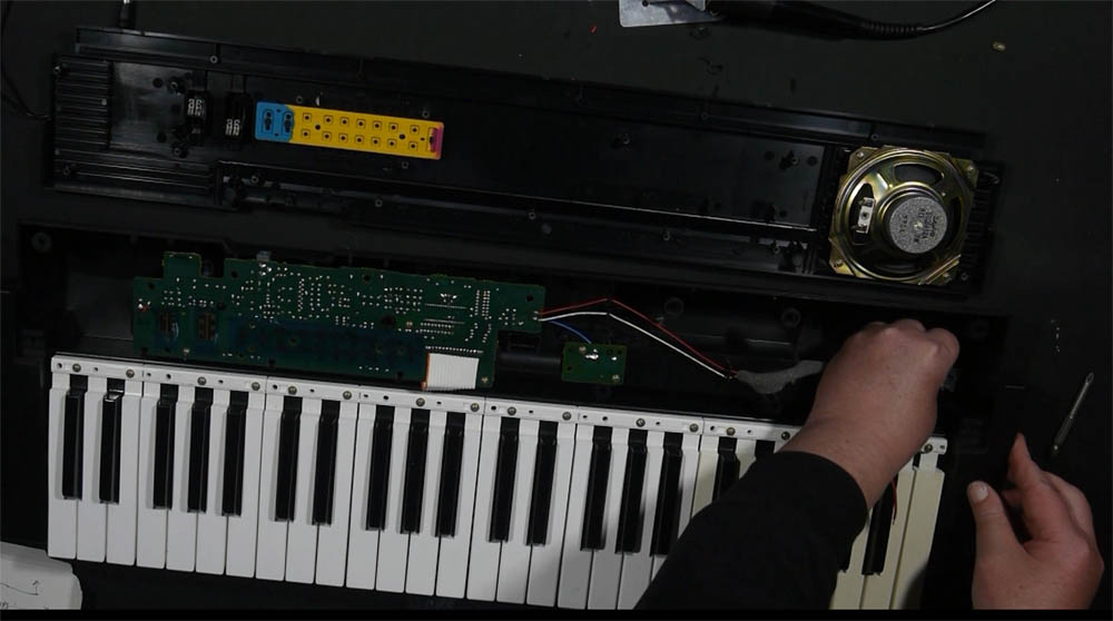
The first thing I did was to remove the wires from the speaker and extend them, Casio was being extremely economical (stingy) with wire in this design so the wires were all under tension when I opened it up.
Incidentally at this point I noticed that they had included a 3w speaker in place of the 2w speaker shown in the schematic. So if you simply wanted to make it louder there is some leeway – though you might want to set it up with something less mediocre than the printed carbon traces the volume switch currently uses.

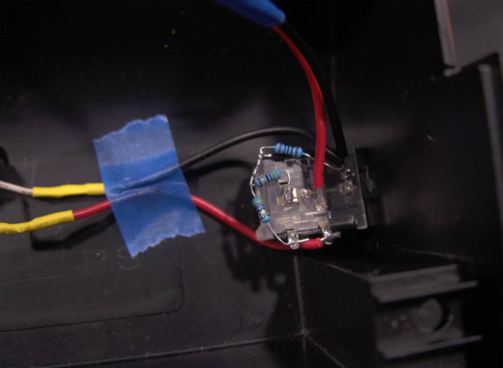
With the headphone jack in place I’m now able to begin setting up the voltage divider which will drive the headphone jack… But first.


NOTE: This is not the best method of putting a headphone jack into an audio device. The best method is for a competent electrical engineer to have designed a headphone jack into the circuit in the first place. This is kind of hacky, and I wouldn’t use it for high powered or expensive devices, but if you just want to get a headphone line out of a toy then this should work. Your mileage may vary. Don’t blame me if you blow something up. Remember to hold the soldering iron by the cold end.
If your headphone coils are significantly higher or lower resistance than mine, you may need to fiddle the values.

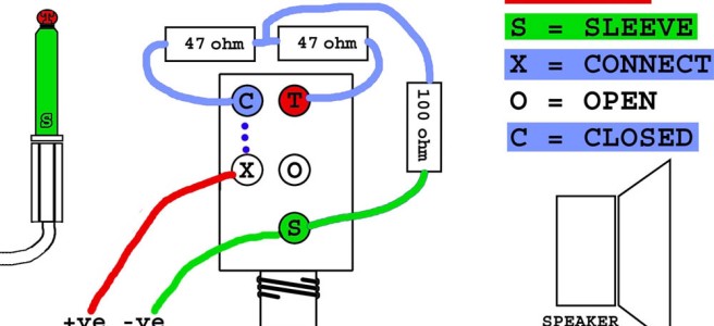
Essentially what these resistors do is to soften down a hot signal. The two 47ohm resistors put a total of 94ohm resistance into the positive line, and the 100 ohm resistor in the middle bleeds off any power that creates undue inductance/resistance on the headphone line – kinda like a pressure relief valve if the headphone line gets too hot.
Basically if the headphones fight back the excess power is just bled to ground.

The signal is coming from the keyboard, through the resistors, to the tip of the headphone jack, from there out through the headphones (turning power into noise) and back through the ground pin to the keyboard ground.
This is the pinout of the actual mono jack I use. It is a switching jack which connects pin x to different pins depending whether a plug is inserted into the jack or not.
In either case the keyboard positive speaker line is connected to the pin marked X.
If the plug is inserted (see above), the audio signal attached to pin X will be routed to pin C (for closed), and thus it will be sent through the divider circuit at a lower power which is more appropriate for headphones.
If there is no plug inserted the X pin will instead be connected to the pin marked O (for open) – this is the pin I am connecting the speaker to (see below). Thus if there is no headphone plug inserted, the signal will be sent to the speaker, just like normal.
Thus inserting a plug will switch off the main speaker. If you want both to be active then you’ll want to solder a bridge between X and O (or a wire with a switch if you want the option to switch it back) – this will mess with the volume for both.


So now I have a keyboard which I can operate for my own quiet enjoyment at any (antisocial) hour of the day.
Win!
