

A few times in my life I’ve had problems sleeping. It’s been many years now since I’ve had insomnia, I suspect that it had more to do with drinking too much coffee and smoking cigarettes back then than any medical factor.
These days I have issues more with sleeping very lightly and waking up multiple times a night. When I wake up I often have no idea what the time is, and any effort to try and figure it out has a tendency to wake me up fully. Thus I have an unfortunate habit of getting up at two or three in the morning, which kinda sucks.
So I had an idea, How about I set up a device which has a traffic light system of showing a red light to indicate that it’s still the middle of the night. A green light to show that I may as well get up if I’m already awake, and a blue light which indicates that I’ve had plenty of sleep. Just press a button when I go to bed and then I’ll know when I should just go back to sleep.
I’m also very aware that different colours of light have effects on circadian sleep patterns. Most people know about the idea that you sleep better if you avoid televisions and screens late at night. This is the blue light that signals to your brain that it’s the middle of the day and thus time to be active. One thing that I do personally is to have a CT lighting gel over my bedside lamp, thus converting it to a very warm yellow light which blocks any blue from the LED in the lamp.
This is why I chose to use red as the signal colour that it’s still time to be sleeping, I was aware that red light has been studied in the context of sleep patterns. Though in the first instance I was using the red light to avoid changing my sleep patterns rather than to hack them.
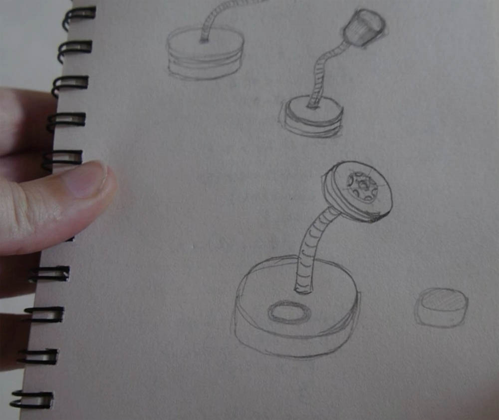
So fired up my sketch book.


Initially I was thinking in terms of a literal timer, I pretty quickly discarded this concept, the other options are a range of basic geometric shapes. I was just throwing ideas at a wall to see what stuck – the 3d print was a quick excercise (followed by a very slow print :P)

I quite like the idea of a cats head on a dual swivel stand – not a practical solution to the problem at hand, but it amuses me.

and I really like this gauntlet type idea where the light will dim according to a mechanical control as you close it down. Again not a practical solution, but I’ll probably come back to it in another project I’m doing using light dimmers.

I even figured out how the mechanism works.
These ideas had their own spin off project emerge – more led dimming stuff, only for filming macro stuff in this case.

After a bit of time noodling about and getting ideas out of my system, I figured I’d just design the circuit and then let form follow function, this is a small atmel microcontroller – It could be argued that I could have done it with several 555’s but I can’t be bothered doing the maths. Much easier to just tell the chip what to do.

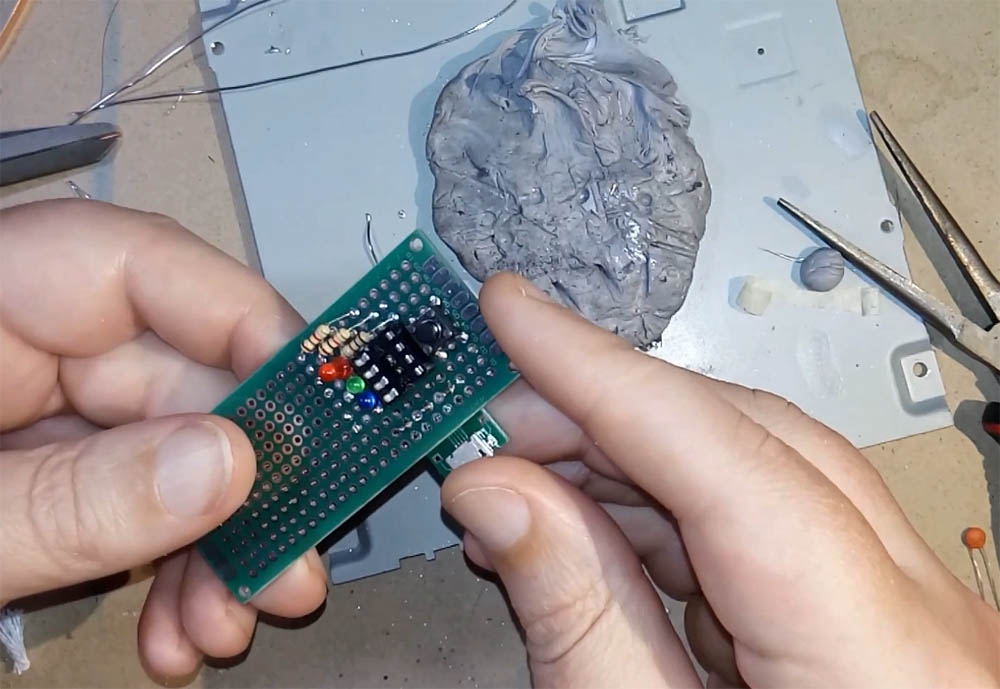
The above isn’t a practical experiment – I just got curious to know how easy it is to solder 0805 smd components onto a dip chip without any supporting circuit board in play. Fairly easy as it turns out, though I should have used copper tape as a matrix, that would have made it dead easy. This wasn’t even a functional prototype, I used a 555 chip for the experiment. so it does nothing.
Why do this?

Yeah, I wrote that in my sketch book too.
In a project like this, it’s all playtime, so I don’t have to succeed. Therefore there’s no real penalty for screwing stuff up. I also learn faster from screwing stuff up than i do from getting stuff right.
So yeah, if I’m noodling away in a sketchbook and suddenly wonder how hard it is to make a tiny widget like the above. If I have the time up my sleeve then I may as well do it, that way I’ll know the answer.
Once I got that out of my system I made a proper one which is designed to actually function. I’m using a dip socket so I can program the chip externally without having to worry about the programming circuitry.
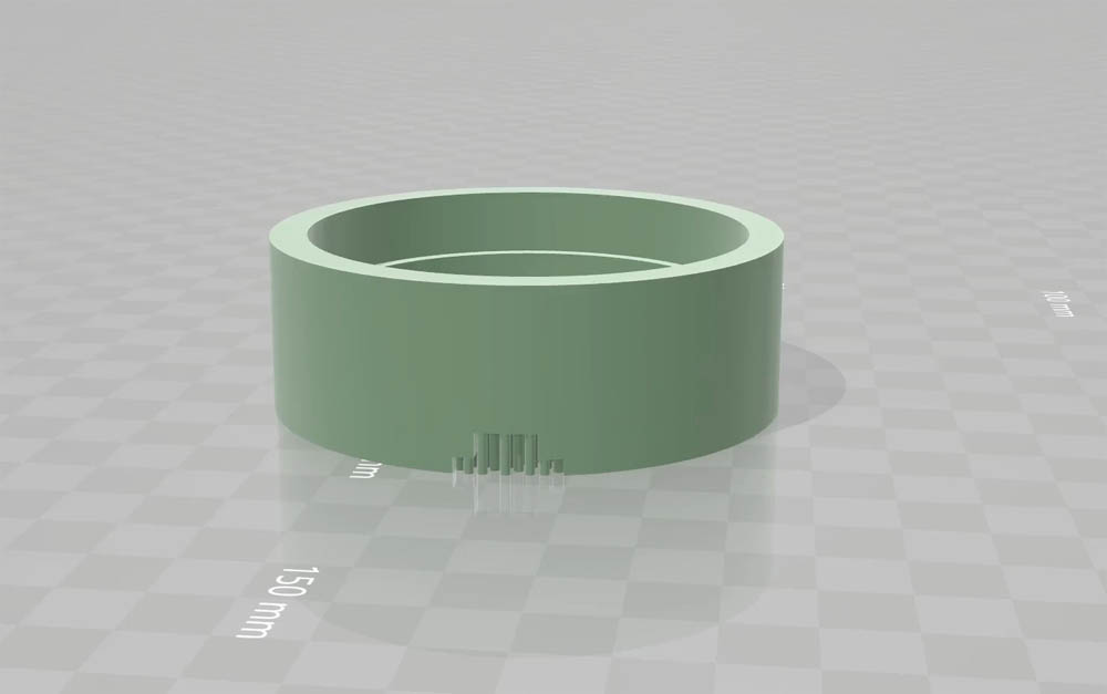
Once I trimmed that down I took a few measurements and then made a 3d model – the rods on the bottom of the front edge are to be snipped out so that the usb header can be press fit in the gap.

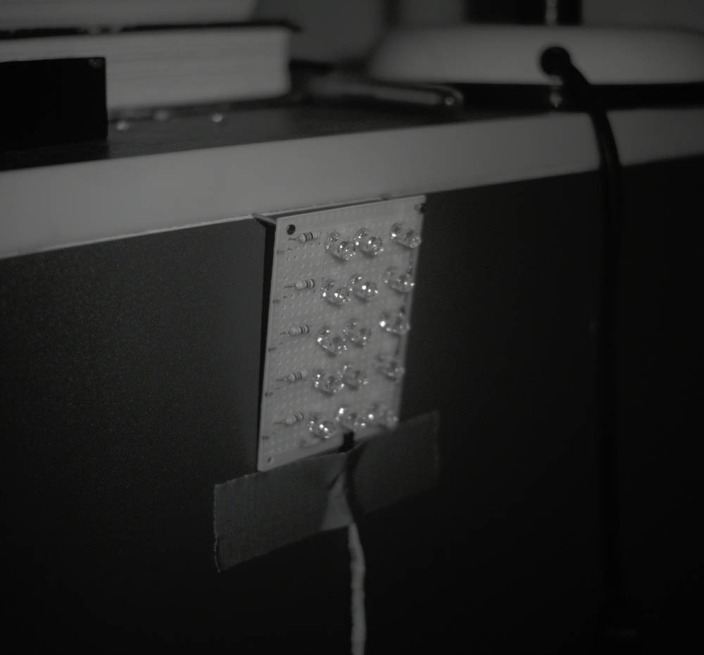
Press fitting the board in place and taping it down. It actually locks in place fairly well.

With the board in place and powered.
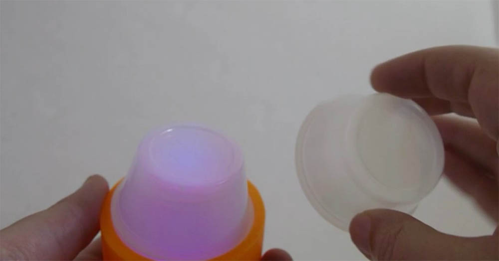
Then I popped a couple of mixing pottles in place on the top to act as a diffuser. In normal lighting this looks pretty dim, but at night it seems a lot brighter.

Good enough for testing.
So debrief;
How long have I played with this? About two years on and off, it’s hard to do experiments in which success predicates you being unconsious, it’s a slow process.
Was it worth it? Oddly yes, My observation personally is that after an initial training period I have associated the red light with sleep time. This has had the effect of basically eliminating the sleep problem which triggered the build.
Will I keep working on it? I already have, I’ve made a V.2, though funnily enough I can’t show that here as I’ve given it to a friend who also suffers from waking up fully at stupid hours of the night. I’m currently looking at a V.3 which incorporates shorter bursts of near infrared light and more intense red lighting instead of green light. This is based on ideas about actually manipulating circadian rhythms instead of simply trying not to disrupt them when I wake naturally.

And yes I nailed and gaffa taped it to my bedside cabinet. Science.
What will/would I do Different? As just mentioned, I’m more interested right now in how easy it is to hack circadian rhythms for profit. If it’s possible to improve sleep with light frequency then it seems like a no brainer to explore it. If not for gain, then at least for better sleep.
Is it a commercially viable idea? Yeah/Nah? Not really, or at least, not for me. After all, it’s really just a blinky light in a case, that’s not a thing that anybody with half a brain would want to bring to market – it’d get ripped off instantly. That’s not to say that it doesn’t work, one of my relations studies sleep science and this is the sort of thing they investigate. I’m reasonably certain now that the red plus infrared light combination has a definite effect on circadian rhythms but I need to do more work on it.
Experiments are ongoing.
-~-
Code for Arduino folllows (the chip is attiny13a, but this code will work in any arduino so long as you re-assign the pins approipriately). It’s really just an led blink circuit in a 3d printed case, nothing too clever. WordPress will mess the formatting up.
// PROGRAM TO USE AN ATTINY13A AS A TIMER FOR A night LIGHT
// (ARDUINO 1.8.4 USING MICROCORE MCUDUDE 1.0.3 ATTINY13 LIBRARY)
// HARDWARE = PUSH BUTTON AND3 LEDs
// colour changes over time to indicate sleep time.
// SECRETIVE SQUIRREL STUDIOS – MAR 2019.
//Sketch uses 344 bytes (33%) of program storage space. Maximum is 1024 bytes.
//Global variables use 5 bytes (7%) of dynamic memory, leaving 59 bytes for local variables. Maximum is 64 bytes.
//——————————————————————-
//Using arduino as ISP
//Reset pin is physical pin 1 on attiny13a – d10 arduino
//Program pin 0 is physical pin 5 on attiny13a – d13 arduino
//Program pin 1 is physical pin 6 on attiny13a – d12 arduino
//Program pin 2 is physical pin 7 on attiny13a – d11 arduino
//Program pin 3 is physical pin 4 on attiny13a
//Program pin 4 is physical pin 3 on attiny13a
//——————————————————————-
// PIN ALLOCATION – CONSTANTS
const byte buttonPin = 3; // the pin of the push button
const byte red = 1; // physical pin 5 – red LED pin
const byte green = 0; // physical pin 6 – green LED pin
const byte blue = 2; // physical pin 7 – blue LED pin
// VARIABLES
byte count = 0; //hours for count
void setup() {
// initialize the LED pins as an outputs:
pinMode(red, OUTPUT);
pinMode(green, OUTPUT);
pinMode(blue, OUTPUT);
digitalWrite(red, LOW); //make sure they’re off
digitalWrite(green, LOW);
digitalWrite(blue, LOW);
}
// RESET BUTTON STARTS TIMER
void loop() {
begin(); //Function to start led’s
}
//————————————————————————-
void begin() { // begin counting down, red for 6hr, green for 1 hr, then stay blue
//TURN ON RED LED FOR 7HR
while (count < 7) { // if number is greater than SIX HOURS digitalWrite(red, HIGH); // then user has entered & is ready to expose for (byte i = 60 ; i > 0 ; i–) { // FOR SIXTY MINUTES
delay(60250); // turn/leave the LED on for another minute
} //250 allows for clock cycles
count += 1; // SUBTRACT ONE HOUR (Count Down)
}
digitalWrite(red, LOW); // then turn LED off
//————————————————————————-
// THEN SWITCH TO GREEN FOR ONE HOUR
while (count < 8) { // if number is greater than TWO digitalWrite(green, HIGH); // then user has entered & is ready to expose for (byte j = 60 ; j > 0 ; j–) {
delay(60250); // turn/leave the LED on for another minute
} //250 allows for clock cycles
count += 1; // remove one from hour count (Count Down)
}
digitalWrite(green, LOW); // then turn LED off – and reset the timer
hold();
}
//————————————————————————-
// THEN TURN ON THE BLUE LED AND WAIT
void hold() {
while (count > 0) {
digitalWrite(blue, HIGH); // then user has entered & is ready to expose
delay(60250); // turn/leave the LED on for another minute
// NOTE – DOES NOT COUNT DOWN, STAYS ON FOR EVER
}
}
